Circuit digital Jk ff circuit diagram Solved show the design of a jk-ff using a t-ff. your answer
Jk Ff Circuit Diagram
[solved] convert j-k ff to t ff. show the conversion process clearly T flip-flop explained T flip-flop explained
Solved 4- design a digital circuit with t−ff, whose state
Solved q4 [10]: design of the fsm using t-ff for the givenSolved design a sequential circuit using t ff where the Circuit diagram of the t-ff test circuit for measuring the maximumSr flip flop explained.
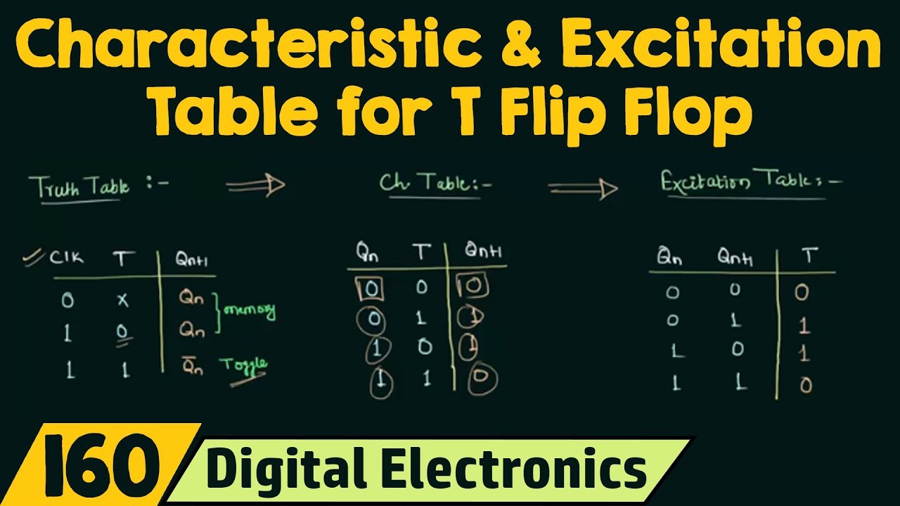
T flip flop circuit diagram and truth tableCircuit diagram of the t-ff test circuit for measuring the maximum Circuit diagram of the t-ff test circuit for measuring the maximumWhat is excitation table? list the excitation table for sr-ff, jk-ff d.

Given the t-ff circuit (left), complete the timing waveform diagram in
Solved given the negative edge-triggered t-ff circuit shownDesign jk flip flop using t flip flop Solved using a t-ff create the following circuit:Circuit diagram of the super-dynamic t-ff..
Solved given the t-ff circuit shown in figure 1 (left)Solved question 1 a circuit using t-ff is given. identify Truth table of t flip flopsT flip-flop circuit using 74hc74.

Analysis of counter circuits
T flip flop diagram and truth tableT flip flop circuit diagram and truth table Flip flop truth table circuit using sr working circuits 74hc00 jk data binary diy inputsToggle flip flop circuit diagram.
T flip flopSolved using two of the t ff's shown below, draw a modulo-4 Flip flop logic conversion types their diag geeksforgeeks applicationsMaximum measuring.
Phase diagram of the fe-ti system proposed in the sgte alloy database
T flip-flop explainedFlip-flop types and their conversion Alloy sgte proposedSequential circuits part-v.
(a) when t ≤ t f, equivalent circuit for the output voltage. (b) when t .


Solved Question 1 A circuit using T-FF is given. Identify | Chegg.com

Solved Given the negative edge-triggered T-FF circuit shown | Chegg.com

Circuit diagram of the T-FF test circuit for measuring the maximum

T Flip Flop Circuit Diagram And Truth Table

Sequential Circuits Part-V

Solved - Using a T-FF create the following circuit: | В 1 1 | Chegg.com

Jk Ff Circuit Diagram

SR Flip Flop Explained | Truth Table and Characteristic Equation of SR